mmWave Radio
Design and Implementation of IBM’s 28GHz PAAMs and their Integration in the COSMOS Testbed
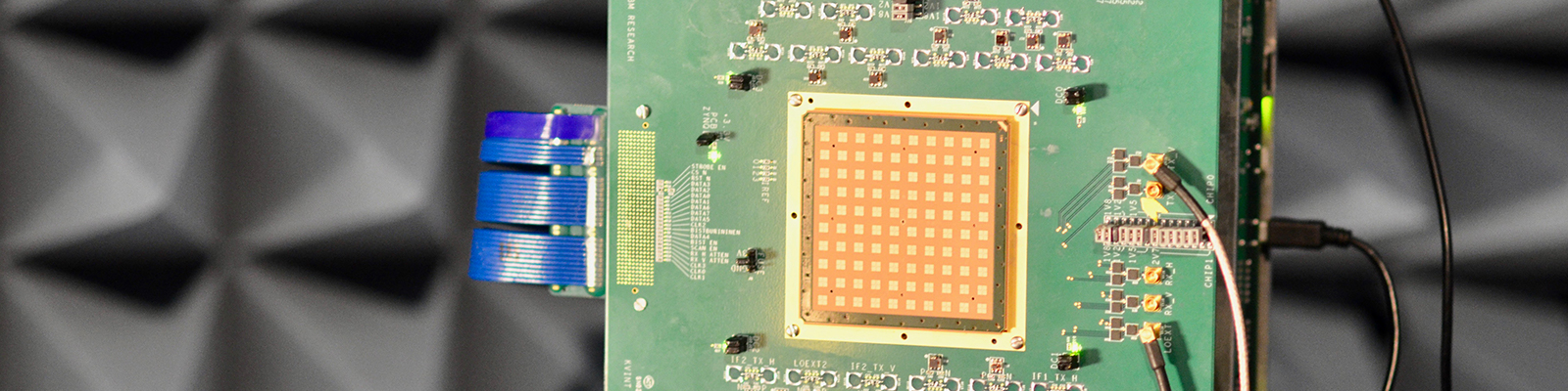
A key feature of the COSMOS platform is the integration of fully-programmable, high-performance SDR nodes with mmWave phased arrays. While there has been significant industrial and academic research on silicon-based mmWave phased array RFICs dating back to 2004, it is only recently that we are seeing commercial-grade mmWave phased arrays suitable for deployment in testbeds. Leveraging our ongoing partnership with IBM, the COSMOS platform will include mmWave nodes operating at both 28 and 60 GHz. The IBM 28GHz phased-array antenna module (PAAM), as shown in Figure 1, features 4 tiled RFICs supporting 64 dual-polarized antennas, 8 beams enabling hybrid analog-digital beamforming and MIMO, 30 degrees steerable beamwidth, 43 dBm EIRP, and up to 3 GHz IF. Another key aspect of the IBM 28GHz PAAM is the orthogonal amplitude and phase control enabled by (i) a gain-invariant phase-shifter design and phase-invariant variable-gain amplifier, and (ii) a careful antenna-array-in-package design the eliminates gain and phase mismatches. The front-end will offer rich programmability, including full access to the beamforming control, and latency as low as 10s of ns for low latency MAC and hybrid beamforming.
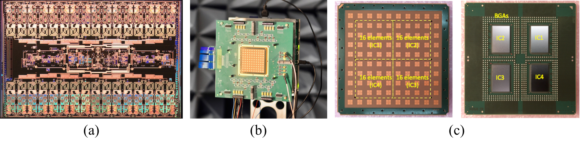
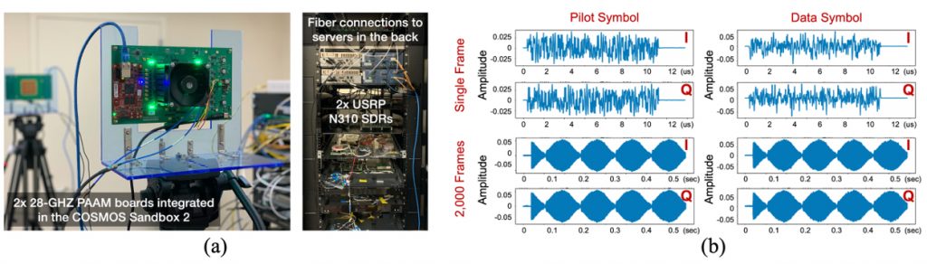
Recently, an improved version of the compact and highly programmable 28-GHz PAAM subsystem has been developed and is currently being integrated in COSMOS [2] leveraging our ongoing partnership with IBM. This subsystem hardware consists of a 28-GHz 64-element state-of-the-art dual-polarized PAAM, low-noise DC-DC power regulators with a single 12-V input, current sensors and an ADC for real-time supply monitoring, a phased-locked loop (PLL) for local oscillator LO (5 GHz) generation, intermediate frequency (IF) (3 GHz)/LO splitters, IF/LO baluns, and programmable switches. All of these components are integrated in a compact (10” x 5.75”) printed circuit board (PCB), which also supports the direct plug-in of a commercial-off-the-shelf FPGA system-on-module (SoM). The IF switches and splitters couple the PAAM to 20 IF ports that enable a rich set of multiple-input multiple-output MIMO configurations, including up to 8 simultaneous 16-element independent beams in each TX/RX mode. The FPGA and associated software enable the configuration of all subsystem features from a high-level application program interface (API), facilitating MIMO millimeter-wave wireless experiments. 28-GHz channel sounding measurements using the phased array subsystem coupled with software-defined radios (SDRs) is presented as a testbed-level experiment example, as shown Figure 2.
[1] B. Sadhu, Y. Tousi, J. Hallin, S. Sahl, S. Reynolds, O. Renstrom, K. Sjogren, O. Haapalahti, N. Mazor, B. Bokinge, G. Weibull, H. Bengtsson, A. Carlinger, E. Westesson, J. Thillberg, L. Rexberg, M. Yeck, X. Gu, M. Ferriss, D. Liu, D. Friedman, and A. Valdes-Garcia, “A 28-GHz 32-element TRX phased-array IC with concurrent dual-polarized operation and orthogonal phase and gain control for 5G communications.” IEEE Journal of Solid-State Circuits, vol. 52, no. 12, pp. 3373-3391, Dec. 2017.
[2] X. Gu, A. Paidimarri, B. Sadhu, C. Baks, S. Lukashov, M. Yeck, Y. Kwark, T. Chen, G. Zussman, I. Seskar, and A. Valdes-Garcia, “Development of a compact 28-GHz software-defined phased array for a city-scale wireless research testbed,” in Proc. IEEE International Microwave Symposium (IMS’21), June 2021. [download] Finalist of IMS’21 Advanced Practice Paper Competition (APPC)
[3] T. Chen, P. Maddala, P. Skrimponis, J. Kolodziejski, X. Gu, A. Paidimarri, S. Rangan, G. Zussman, and I. Seskar, “Programmable and open-access millimeter-wave radios in the PAWR COSMOS testbed,” in Proc. ACM MobiCom’21 Workshop on Wireless Network Testbeds, Experimental evaluation & CHaracterization (WiNTECH’21), 2021. [download] [presentation]
28GHz Channel Measurements in the COSMOS Testbed Area
The operation of mmWave networks will require accurate channel models designed for specific deployment sites since mmWave radio signals experience high path loss. In collaboration with Nokia Bell Labs, we conducted and reported extensive 28 GHz channel measurements in the COSMOS testbed deployment area in a multitude of different scenarios [4-7].
Outdoor-to-Outdoor Measurements
The COSMOS testbed area is a representative urban street canyon environment with both line-of-sight (LOS) and non-LOS (NLOS) links. In particular, we considered 3 sites that emulate different deployment scenarios of a mmWave base station (BS): (i) a 15 m-high balcony at a 4-way street intersection (referred to as “Intersection Balcony [Int]”), (ii) a 6 m-high bridge over-crossing an avenue (referred to as “Bridge [Bri]”), and (iii) a 15 m-high balcony facing a park (referred to as “Open Balcony [Bal]”). Our measurement campaign includes over 1,500 link measurements (with over 24 million power measurements) collected along 13 sidewalks adjacent to the 3 considered measurement sites. [4, 5]

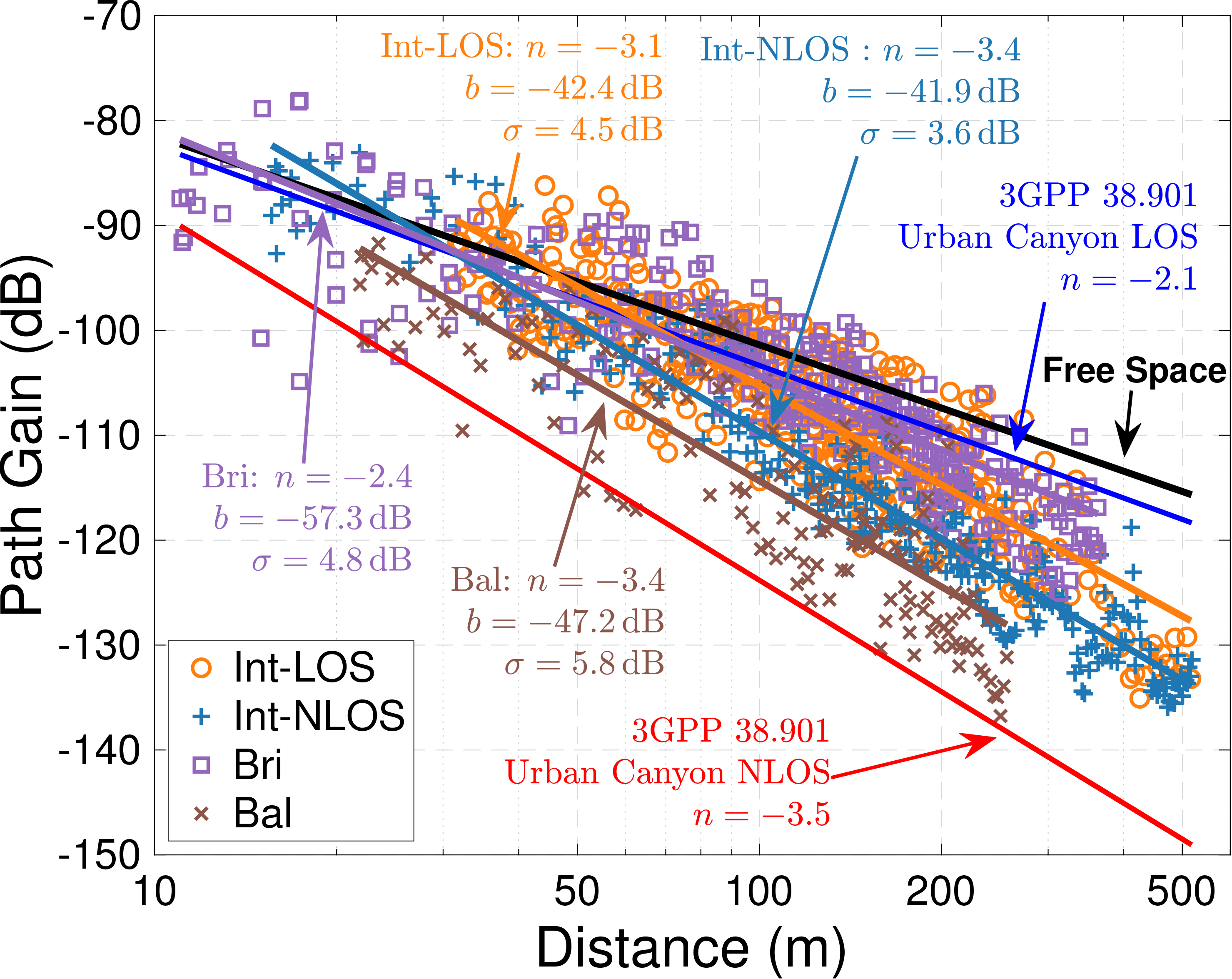
(Left) Locations and example street views of the three measurement sites in the COSMOS testbed deployment area. The receiver (Rx) is placed at a fixed location in each site (marked by a circle), and the transmitter (Tx) is moved along the measurement sidewalks (marked by lines). Solid and dashed lines correspond to sidewalks (or part of the sidewalks) where the Tx and Rx are in line-of-sight (LOS) and non-line-of-sight (NLOS), respectively. (Right) Measured path gain values and the corresponding fitted lines for different sidewalk groups (Int-LOS, Int-NLOS, Bri, and Bal).
Outdoor-to-Indoor Measurements
The Morningside Heights and West Harlem neighbourhoods around the COSMOS deployment area are home to a highly diverse set of building types and use cases. As the mmWave signal will be further hindered by building walls and windows, an indoor user may experience significantly worse coverage. The paper describes over 2,200 link measurements across seven different buildings, accounting for over 32 million power measurements [6, 7]. These buildings include two modern office and laboratory buildings, three older classroom buildings, a student resource centre, and a public middle school, which are shown in the measurement map in the left figure below. The measurements at the public middle school are available at the following dataset , and demonstrate the strong opportunity for indoor coverage by a mmWave BS due to the older, thinner windows used in construction.
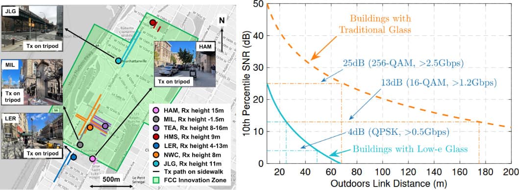
(Left) Map of measurement campaign. The channel sounder receiver (Rx) was placed in the seven marked buildings and the mmWave transmitter (Tx) moved along the marked paths, for a total of 40 scenarios. (Right) signal-to-noise ratio (SNR) against Tx-Rx distance for buildings with traditional glass (like HGMS) and buildings with Low-e glass, typically used in modern building construction. Traditional glass is significantly less lossy, leading to higher SNR and data rates in excess of 2.5 Gbps.
[4] T. Chen, M. Kohli, T. Dai, A. D. Estigarribia, D. Chizhik, J. Du, R. Feick, R. Valenzuela, and G. Zussman, “28GHz channel measurements in the COSMOS testbed deployment area,” in Proc. ACM MobiCom’19 Workshop on Millimeter-Wave Networks and Sensing Systems (mmNets), 2019. [download] [presentation]
[5] J. Du, D. Chizhik, R. Valenzuela, R. Feick, G. Castro, M. Rodriguez, T. Chen, M. Kohli, and G. Zussman, “Directional measurements in urban street canyons from macro rooftop sites at 28 GHz for 90% outdoor coverage,” IEEE Transactions on Antenna and Propagation, vol. 69, no. 6, pp. 3459–3469, June 2021. [download]