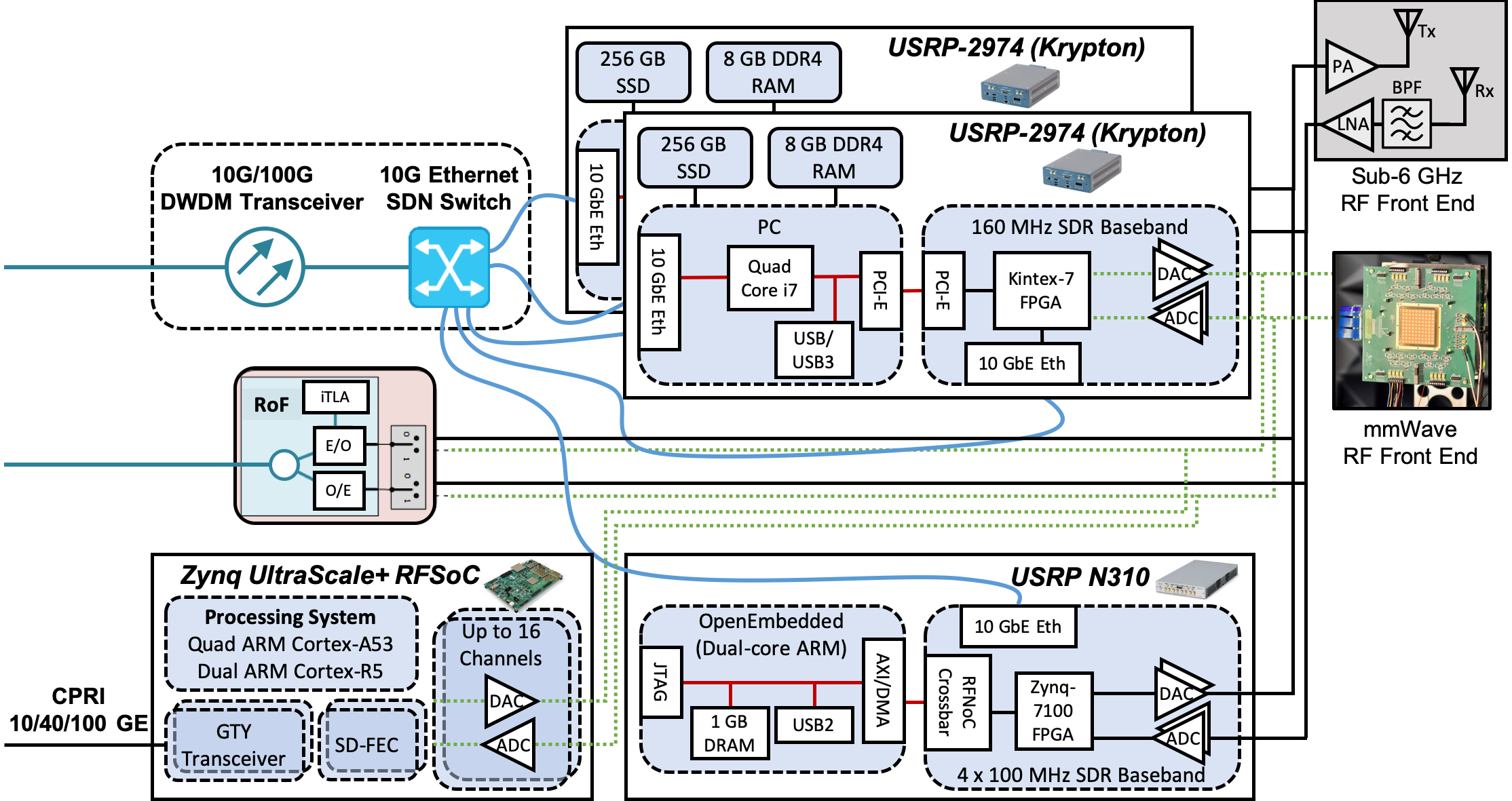
The COSMOS radio node is an FPGA-assisted software radio design based on a number of COTS components (USRP, RFSoC, etc). The design supports multiple RF front ends including sub-6 GHz and mmWave. The node can be also expanded with additional COTS modules in order to support general purpose legacy services and control requirements. In addition to communication functions, each node can incorporate RF sensing and signal measurement capabilities to support (dynamic) spectrum use and propagation studies. The nodes are available in three form factors, small, medium and large, for mobile, street-level and rooftop installations respectively. The same general components are used for all three sizes, with differences due to the number of antennas supported, radio frequency bands and bandwidth covered, and level of SDR processing provided. These SDR radio nodes work in conjunction with computation on edge cloud servers that can be set up to take on a portion of the signal processing. The figure below shows an example block diagram of an SDR node, where different node configurations include a subset of the components.
Example block diagram of a medium node or a sector of a large node, where different node configurations include a subset of the major components (e.g., sub-6/28 GHz RF front ends, FPGA-assisted SDRs, and radio over fiber [RoF] interface).
Large Node
The large node, as a relatively complex COSMOS piece of equipment, is typically installed on a building roof, and is composed of a number of the following components:
number of sub-6GHz transceivers potentially with multiple RF front-ends
number of mmWave transceivers
modest local edge cloud resources
number of mmWave and FoS of the shelf point-to-point (ptp) devices
optical/SDN node with accompanying fiber infrastructure
number of COTS legacy infrastructure devices (i.e. LTE eNodeB, IoT base station, long-rage WiFi AP, etc.).
The deployment also requires custom power distribution installation as well as RF and optical cable trays distributing corresponding signals to various rooftop antenna locations that will be determined based on the overall RF planning and coverage analysis as well as on various backhauling/multi-pathing requirements.
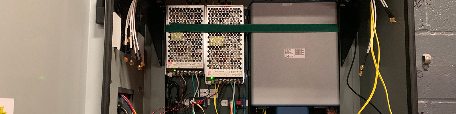
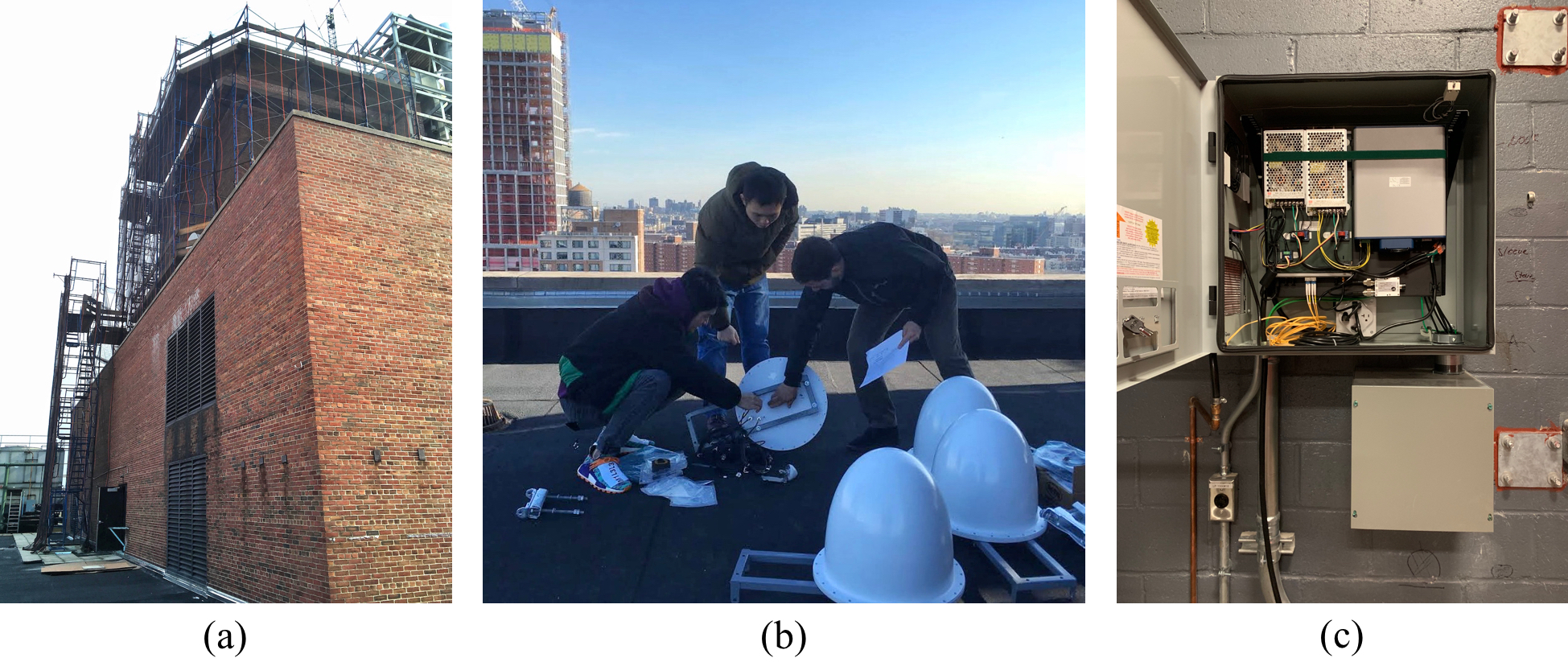
(a) COSMOS' pilot large node on the Mudd building rooftop at Columbia, (b) sub-6GHz wideband directional antennas for the large node, and (c) SDRs, RF front-ends, Ethernet/optical switches included in a large node sector.
Medium Node
The unit contains up to three computational elements with a number of SDR transceivers (either Sub-6GHz or mmWave or both) with at least one of the sub-6GHz SDR SDRs used for spectrum monitoring.In addition to standard peripherals that can be attached to each of the local computational elements (like WiFi, Bluetooth, Z-Wave, etc.), it also contains high performance small port count SDN capable Ethernet switch with a number of DWDM transcievers, Each unit also has complex chassis manager (CM) allowing for independent on/off control for each motherboard/device. The node is housed in a custom weatherproof enclosure designed for lamppost/side-of-the-building deployment and will consume up to 600W. A number of high-performance of the shelf point-to-point mmWave radios and/or free space optics (FoS) devices acn also be attached to the enclosure providing backhaul connectivity for street level locations without fiber and/or multi-homing/multi-pathing experimentation capabilities for nodes with multiple backhauls.
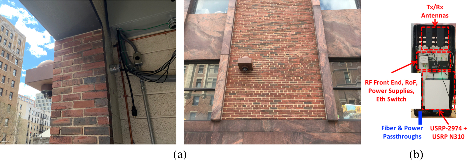
(a) Antenna and camera of COSMOS' two pilot medium nodes on the 100- and 200-level of the Mudd building at Columbia, and (b) prototype of the light version of the medium node for lightpole mounting (medium-light) with the components layout.
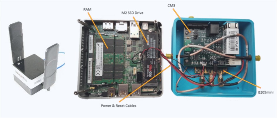
Small Node
The core of the small (portable) node is based on small-form-factor PC (i.e. Intel NUC based platform) with number of internal peripherals (solid-state storage, AC WiFi, Bluetooth, etc.) as well as external peripherals (USB3 attached custom sensor pack, 4G modem, etc.) – see Figure below. The compartment below the main board contains a management unit (CM), small sub-6GHz SDR and a battery pack with the electronics supporting variety of power sources. The whole package it is roughly 4 inches on a side and consumes between 40W and 80W (depending on the choice of CPU and peripherals/sensors) simplifying in vehicle installation and even enabling backpack type deployments.